Difference between revisions of "PAL0123"
(added information) |
(added datasheets, new picture and todo) |
||
| Line 9: | Line 9: | ||
[[User:Xopr|xopr]] received two 192x16 bicolor 5mm dot matrix displays (one to keep, one to fix a controller board for). | [[User:Xopr|xopr]] received two 192x16 bicolor 5mm dot matrix displays (one to keep, one to fix a controller board for). | ||
=== used ICs === | === used ICs === | ||
| − | * DM74LS138N decoder/demultiplexer | + | * [[File:DM74LS138N.pdf|DM74LS138N]] decoder/demultiplexer |
| − | * M74HCT245B1 octal bus transceiver | + | * [[File:M74HCT245B1.pdf|M74HCT245B1]] octal bus transceiver |
| − | * MBI5016CNS 16 bit constant current LED sink driver | + | * [[File:MBI5016CNS.pdf|MBI5016CNS]] 16 bit constant current LED sink driver |
=== pinout and protocol === | === pinout and protocol === | ||
| Line 18: | Line 18: | ||
The display is controlled with 9 bits (red, green, clock, strobe, latch enable, a, b, c, row) | The display is controlled with 9 bits (red, green, clock, strobe, latch enable, a, b, c, row) | ||
| − | Pinout | + | Pinout (this is having the header at the left facing you, having the display put upside down (facing the other way) |
<pre> | <pre> | ||
pin 1 | pin 1 | ||
| Line 40: | Line 40: | ||
Did some tests with an [[ESP|ESP-12E]] module and had some success (the 'ROW/chip select' pin selecting the other 8 rows somehow failed on GPIO15 and GPIO16). | Did some tests with an [[ESP|ESP-12E]] module and had some success (the 'ROW/chip select' pin selecting the other 8 rows somehow failed on GPIO15 and GPIO16). | ||
[[Image:marquee_on_ESP.jpg|thumb|first PoC (5V logic driven with ESP]] | [[Image:marquee_on_ESP.jpg|thumb|first PoC (5V logic driven with ESP]] | ||
| + | [[Image:ACKspace_w00t_on_ESP.jpg|thumb|some actual text]] | ||
=== todo === | === todo === | ||
| − | * | + | * write some descent code (taking the wifi interrupts into account) |
| − | |||
[[Category:ESP8266]] | [[Category:ESP8266]] | ||
[[Category:Displays]] | [[Category:Displays]] | ||
[[Category:LEDs]] | [[Category:LEDs]] | ||
Revision as of 21:27, 3 September 2015
| Project: PAL0123 | |
|---|---|
| Featured: | |
| State | Active |
| Members | xopr |
| GitHub | No GitHub project defined. Add your project here. |
| Description | 192x16 bicolor matrix display |
| Picture | |
| No project picture! Fill in form Picture or Upload a jpeg here | |
Contents
PALTRONICS PAL0123 REV 0 (1998) 192x16 bicolor matrix display
synopsis
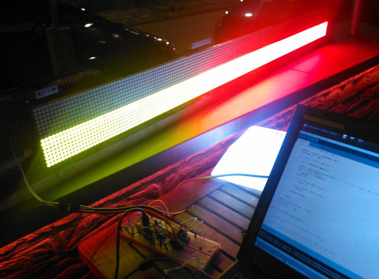
xopr received two 192x16 bicolor 5mm dot matrix displays (one to keep, one to fix a controller board for).
used ICs
- File:DM74LS138N.pdf decoder/demultiplexer
- File:M74HCT245B1.pdf octal bus transceiver
- File:MBI5016CNS.pdf 16 bit constant current LED sink driver
pinout and protocol
The marquee consists of shift registers which allows one to shift and latch in 2x192 bits. After that's done, a row needs to be selected and the two colors are displayed with a strobe signal. This means, the display has no memory and for every line, a new set of pixels need to be shifted in. The display is controlled with 9 bits (red, green, clock, strobe, latch enable, a, b, c, row)
Pinout (this is having the header at the left facing you, having the display put upside down (facing the other way)
pin 1
    .--.
GND |oo| Red
GND |oo| Green
GND |oo| CLK
GND |oo| LE
GND |oo| C
GND |oo| B
GND |oo| A
GND |oo| Strobe
GND |oo| Row
NC  |oo| NC(?)
    '--'
plan
Already reverse engineered the pinout and protocol and drove it with an arduino nano. Unfortunately, with the default settings, it is slow enough that the display's refresh rate becomes annoying. Did some tests with an ESP-12E module and had some success (the 'ROW/chip select' pin selecting the other 8 rows somehow failed on GPIO15 and GPIO16).
todo
- write some descent code (taking the wifi interrupts into account)
