Difference between revisions of "Emergency Brake Light driver"
(→Introduction) |
m (set project picture) |
||
| (6 intermediate revisions by 2 users not shown) | |||
| Line 1: | Line 1: | ||
{{Project | {{Project | ||
| − | |State= | + | |State=Stalled |
|Members=Danny Witberg | |Members=Danny Witberg | ||
|Description=Make cars less dangerous | |Description=Make cars less dangerous | ||
| + | |Picture=Ebl blockschematic.png | ||
}} | }} | ||
| − | |||
== Introduction == | == Introduction == | ||
| Line 10: | Line 10: | ||
<div style="border: medium none; padding: 1ex; text-align: center;"> | <div style="border: medium none; padding: 1ex; text-align: center;"> | ||
| − | {{#widget: | + | {{#widget:YouTube|id=H9Nww7iBIrM}} |
| − | | | ||
| − | |||
| − | |||
| − | |||
| − | }} | ||
</div> | </div> | ||
| + | |||
| + | This project is used as a driver for the brake light to measure deceleration and, when over a certain level, let the brake light blink. | ||
| + | |||
| + | == Block schematic == | ||
| + | |||
| + | [[File:ebl_blockschematic.png]] | ||
| + | |||
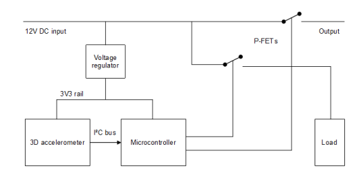
| + | The 12VDC input consists of the original brake light supply, so this device is only powered in case of a brake event. The voltage regulator makes a local 3V3 supply to power the microcontroller and the 3D accelerometer. This sensor is read out by the microcontroller by means of a I²C bus. If the deceleration is under a certain level, the controller only engages the P channel mosfet that drives the actual output: the brake light itself. Over that trip level, the microcontroller alternates between the two mosfets, so that the output blinks. The load is optional in case the car's ECU detects a faulty brake light by sensing the amount of current drawn by the light. In this way, there is a constant current to prevent any brake light warnings generated by the car. | ||
Latest revision as of 17:51, 22 September 2016
| Project: Emergency Brake Light driver | |
|---|---|
| Featured: | |
| State | Stalled |
| Members | Danny Witberg |
| GitHub | No GitHub project defined. Add your project here. |
| Description | Make cars less dangerous |
| Picture | |

| |
Introduction
This project is an enhancement on existing brake light configurations on cars, specifically the third brake light. This usually consists of an array of red LEDs placed higher on the back of the vehicle, to be more in the viewing range of the driver behind the car. This way he can react more quickly if the car in front brakes, therefore helps prevent collisions and helping in general road safety. In more "expensive" cars, if the car brakes firlmy, the third brake light flashes fast to attract even more attention from the person driving behind.
This project is used as a driver for the brake light to measure deceleration and, when over a certain level, let the brake light blink.
Block schematic
The 12VDC input consists of the original brake light supply, so this device is only powered in case of a brake event. The voltage regulator makes a local 3V3 supply to power the microcontroller and the 3D accelerometer. This sensor is read out by the microcontroller by means of a I²C bus. If the deceleration is under a certain level, the controller only engages the P channel mosfet that drives the actual output: the brake light itself. Over that trip level, the microcontroller alternates between the two mosfets, so that the output blinks. The load is optional in case the car's ECU detects a faulty brake light by sensing the amount of current drawn by the light. In this way, there is a constant current to prevent any brake light warnings generated by the car.